I. Introduction
From data centers to industrial facilities, at the heart of many modern electrical systems lies a critical, often overlooked component: the busbar connector. This utility assumes the prime role of power conveyance inside electrical enclosures serving as a steadfast and resourceful alternative to ancient cabling. It is imperative for architects, planners and anybody else involved in or describing electrical framework to understand busbar links, their mechanism, and the various forms present. The article covers how these critical components can be configured differently what functions they have and why they are distinctive – it highlights how such setup helps create a functional optimized electricity network. Firms like NKS Power which manufacture numerous such vital arrangements offer clientele myriad choices when on the lookout for top-notch resolutions.
II. Basics of Busbar Connector
A busbar is a bar or strip made from highly conductive metal-mostly copper or aluminum- designed to carry great amounts of electric current, normally used as the common connection for several incoming and outgoing electrical circuits. A busbar connector is actually specialized hardware used to connect these busbar sections or other components to the actual main busbar system (such as switches, circuit breakers, meters). The primary function of connectors is ensuring a stable low-resistance safe electrical interface. This makes for a more organized and efficient panel layout eliminating the necessity of complex and space-consuming spider webs of single wires. Other advantages include faster mounting time, good heat dissipation, higher mechanical strength, and more flexibility regarding any future changes in the system.
1. Core Components and Materials
The effectiveness of a busbar connector system hinges on the materials used and its construction.
(1) Material choice greatly affects life and current capacity. Due to its great conductivity and low resistance to rust, copper is the most often used. Though it needs a larger cross-section to carry the same current as copper, aluminum is lighter and less costly so it is also used, especially in big uses.
(2) Most new busbar systems come with either insulation or shielding. The insulation can be a simple coat of plastic or epoxy that resists heat, preventing accidental touching of live parts, and increasing safety. The shielding is usually a metal cover that protects against electromagnetic interference (EMI) where sensitivity to such an environment exists as in data centers.
(3) Bolts, nuts, and clamping plates which are mechanical components forming the physical joint must be designed in such a way that they apply adequate pressure to sustain a gas-tight connection. When this is not achieved, oxidation and overheating at the joint occur; this is the most common point of failure in electrical systems.

III. The Working Principle of a Busbar System
A busbar connector system operates with very basic principles, and though the mechanism is quite simple, it relies on some fundamental electrical concepts for effective and safe distribution of energy. Practically, the system operates by providing a continuous low impedance path for current to flow from a source of power to different loads.
1. Establishing a Low-Resistance Path
The resistance at the point of connection should be made as negligible as possible, which is the main purpose of an adequately designed busbar connector. This is enabled by large surface area contact and high clamping force. The connector physically presses the busbar surfaces together to ensure maximum metal-to-metal contact; hence, there will be no voltage drop and power loss (I⊃2;R loss) across the connection. This translates to energy efficiency being better and lower operating temperatures attained.
2. Heat Dissipation and Current Carrying Capacity
A major advantage of using a busbar as compared to a wire of equal rating is the greater provision made for the dissipation of heat. Since it has a large surface area, the heat created by the flow of current will be distributed and thrown off into the surrounding air more efficiently. The busbar can carry higher current for a given cross-sectional area than that which is possible through an insulated cable. Connectors are designed to match this, and in fact, they are usually so massive that they never become thermal bottlenecks.
3. Mechanical Stability and Safety
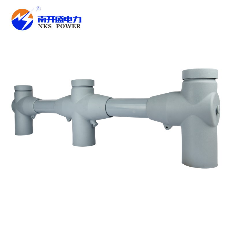
Beyond electrical performance, the working principle extends to mechanical integrity. It must be able to withstand any forces that may be developed due to short circuit conditions. The forces can be quite large and try to separate the conductors. A good connector like a T-type screened top busbar connector will make sure to lock the busbar in place so that there is no accidental disconnection of the busbar which might otherwise create an arc and hence a big safety hazard.

IV. Common Types of Busbar Connectors
Busbar connectors are not one-size-fits-all; they are engineered for specific applications, configurations, and performance requirements. The choice of connector type impacts the ease of installation, maintenance, and overall system functionality.
1. U-Type Busbar Connector System
This is a versatile and widely used design characterized by its U-shaped clamping mechanism.
(1) The U-type busbar connector system typically consists of a U-shaped base that cradles the busbar and a top plate that is bolted down, sandwiching the busbar securely between them. This design is ideal for straight-through connections or tapping off at 90 degrees. It finds common usage in low as well as medium voltage applications because of its simplicity added with reliability.
(2) The primary advantage is its straightforward design, which makes installation and later inspection relatively easy. It provides a large contact surface and can accommodate different busbar thicknesses with minor adjustments.
2. T-Type Connectors
As the name suggests, these connectors are used to create a "T" junction, allowing a branch circuit to tap power from the main busbar run.
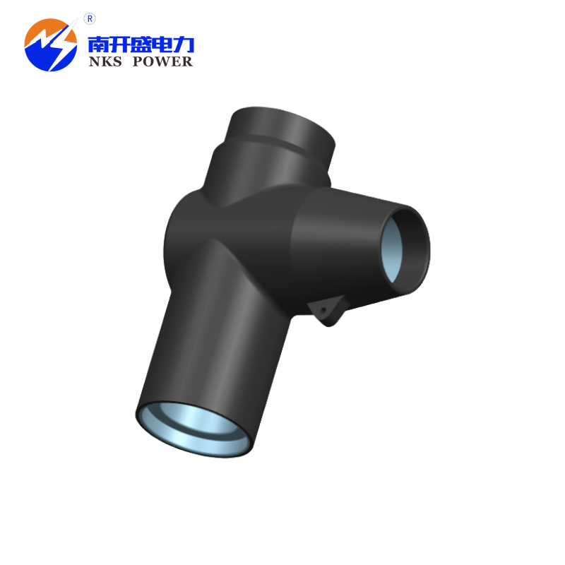
(1) The T-type screened top busbar connector is a developed version in which the whole connection point is covered by metallic shielding. In cases where there is a threat to EMI, such shielding becomes very important. It avoids the emission of electromagnetic noise from the busbar joint that may create disturbances in sensitive electronics around and at the same time protects the connection from any external interferences.
(2) In contrast, the unscreened top busbar connector performs the same T-junction function but without the electromagnetic shielding. This type is suitable for general-purpose industrial applications where EMI is not a primary concern. It offers a cost-effective solution while maintaining the essential electrical and mechanical connection properties.
3. Specialized Connector Types
For more advanced applications, specific connectors may be used. The version of tubes lug type screened top busbar connector serves the purpose of joining cables to the busbar setup. It includes a terminal lug (commonly a tube or ring tongue) which can be attached to a cable by crimping or bolting. This lug is then placed into a shielded housing that links with the busbar making an organized secure and EMI-protected shift from the stiff busbar to flexible wiring for last connections to tools.
V. Conclusion
Busbar connectors are more of the heart in modern electrical engineering than the body. This turns a simple conductive bar into something complex, safe, and very efficient as an energy distribution backbone. Designs go from the basic U-type to EMI-shielded T-type; however, each design has its place toward optimal performance. It offers low resistance, mechanical stability, and thermal efficiency—a connection that helps keep energy losses ever so minimal, ensuring safety while offering long-term reliability of electrical systems in all applications possible—henceforth more vital with every stride forward in technology paired with increasing demands for power. Indeed learning its different types and working principles forms an indispensable triad for practitioners in this domain. Just pick the right components from a busbar connector manufacturer to finish up building up strong electrical infrastructure.


